[av_textblock size=” font_color=” color=”]
Understanding Quadrature Encoding
A quadrature encoder is a type of incremental encoder which has the ability to indicate both position and direction of movement (as well as velocity). This type of encoder is found in numerous consumer and commercial applications. The versatility of quadrature encoding is one of its strengths as they are capable of high resolution, high precision measurement and can work in a wide range of speeds from a few RPMs to some exceeding 5000RPMs. These encoders typically use optical or magnetic (hall-effect) sensors making them extremely durable and easy to utilize. A variety of ways exist to generate quadrature encoded signals, but first we’ll examine the fundamentals of the sensor and how quadrature works.
Fundamentals of the Sensor
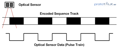
Optical sensor are typically used to read data from an encoded track. A light sensing optical sensor passes over an encoded track as shown in Figure 1 and light and dark segments of the encoded track reflect varying degrees of light back to the sensor. The corresponding data is a high or low signal depending on weather the sensor is seeing light or dark. This generates the resulting pulse train data output (again, refer to Figure 1).
This one bit system has two states, high or low. And by counting these transitions and looking at the time between transitions we can determine the velocity of our system. By looking at the transition between high and low we have enough information to determine velocity. As the track moves faster past the optical sensor, the pulse train will increase in frequency, Figure 2. Likewise, as we slow down, the pulses will get wider (less frequent); no change means the system has come to a full stop. From this stationary state, as the system starts to move again, the pulses return, getting wider as the speed increases. Unfortunately, from this binary one bit system, we can determine velocity, but not position because the direction of rotation is unknown. This lack of direction creates ambiguity (in systems that can change direction), and cannot be used to determine position. An example of an ambiguous pulse train is shown in Figure 3 and this is the limitation of a single sensor/track system; speed but no position.

Figure 3 – Directional Ambiguity of Pulse Train Data
Dealing with Ambiguity
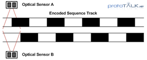
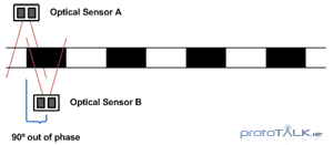
The ambiguity in quadrature encoding is resolved though the additional of another data channel (Figure 4). By offsetting the phase of these two, otherwise identical, tracks by 90 degrees, it establishes two bits of data per cycle (Figure 5). These two channels are referred to as Channel A and Channel B in most quadrature systems.
With Channels A and B, the track defines 4 quadrants or state in which the system resides at any given moment. The change in state is limited to one of two states (the previous or the next quadrant). This form of encoding created by this phase offset is called Grey code encoding where by only one bit can change at any given moment (no point does the data on both channels change at the same time). By comparing the current state against the next state, direction can be inferred (see truth table in Figure 6).
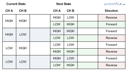
Figure 6 – Quadrature Encoding Direction Truth Table
The 90 deg phase offset essentially causes one of the channels to “follow” the other. So by looking at which channel is leading, the direction can be determined. Figure 7 shows this where in forward motion, Channel B is following Channel A during the first half. When A goes high, B goes high after the phase offset delay; likewise when A goes low, B goes low soon-after. In the second half of the graph, after the change in direction, Channel A follows Channel B indicating that the system is now operating in the reverse direction.
Resolving Ambiguity
Let’s revisit the previously ambiguous case (Figure 3) and see how Channel B (highlighted in blue) resolves ambiguity. In Figure 8, it is now clear that no change in direction occurs because Channel B always follows Channel A. We say follow because Channel B reflects what Channel A is doing, but with a delay. Channel A in this case leads the changes indicating that no change in direction occurred.
Figure 9 is the second case where the direction reverses as indicated where Channel B begins to lead. By examine which channel is leading, we can determine the direction.
Wheel Encoders
Up until now we’ve only looked at linear encoding tracks, and yes this technique does work on linear systems. However, we are also covering rotary encoders so let’s take a look at a few wheels encoders. We’ll look at some different wheel examples and go over the track resolution.
A wheel encoder is simply an encoding track wrapped on the plane of the wheel. Figure 10 is an example of a very basic encoder wheel with only 2 bits of resolution per revolution. The resolution of the encoder wheel is determined by the number of cycles or complete phases. In this case we have two cycles from black to white on Channel A and B, as such, the resolution of this wheel is 2 bits.
This wheel also includes a third bit closest to the center called an index bit. This is sometimes used as a point of reference in rotary encoder systems that support the use of an index bit (typically a 3rd sensor is required to read this bit).
The encoder resolution can be increased by adding more phases to the wheel. In Figure 11 we have a 64 bit encoder wheel. The wheel resolution is 64 bits because of the number of phases. However, since the encoder system uses an 90 degree off-phase signal to provide 4 unique states per phase, the offset provides 4x the resolution meaning it can detect up to 256 position along the wheel!
Sometimes it’s easier to see things in action. Check out this video overview of the Nubotics WheelWatcher showing how the waveforms look on an oscilloscope as the speed and direction changes.
Optimizing the Encoder
As the resolution increases, sensors placement becomes critical. The sensor placement limits the variety of encoder designs and resolutions that can be used and as a result, placement of the sensor often limits the resolution and size. However, because of this correlation, we can look at an optimization that simplifies the encoding by incorporating the 90 degree offset into the sensor placement (Figure 12). As long as the 90 degree offset is maintained, the sensors can be separated by multiples of the cycle width (offset by a phase width in multiples of 360 degrees). This not only removes the need to have a redundant encoder track, but gives greater flexibility in the physical placement of the sensor itself. This idea can be extended to encoder wheels as well flat track encoders, although precautions must be taken in the alignment and orientation (rotation) of the sensors when using a wheel.
Nubotics Wheel Watcher
The Nubotics WheelWatcher quadrature encoders are an example of a single track, offset sensor encoder (Figure 14). The reflective code wheel, superimposed over the sensor (Figure 15), shows that the offset is about 2-3 phase widths in addition to the 90 degree offset. Notice that the sensors are rotated to align with the encoder wheel.
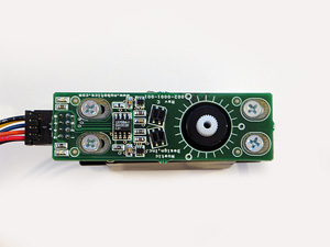 Figure 14 – Nubotics WheelWatcher Encoder |
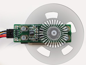 Figure 15 – Encoder with Wheel Overlay |
The Nubotics encoder uses a pair of Omron EE-SY125 reflective photo-detectors to generate the A and B channel signals. An LSI LS7084 Quadrature Clock Converter IC is used to decode the A and B channels to produce direction and clock signals. The clock signal can be useful as it removes the need to decode the signal on a separate microcontroller. The 4x output mode of the LS7084 means that a clock is generated at each transition of the 4 states (per phase). The unit itself makes it easy to get rotational data from popular R/C servos and DC gear motors. This purpose built unit is great for small robotics projects where position, direction, and velocity information is needed. The Nubotics WheelWatcher makes it easy to obtain basic odometry information from a platform for localization and other feedback applications.
Summary
Quadrature encoders are an evolution over single output rotary sensors and their added ability to determine direction greatly improves their functionality. This sensor method makes it possible to add accurate positional feedback into a variety of motor control applications and have already been proven effective in numerous consumer applications as a low cost, simple sensor. The variety in encoder designs and sensor placement allow custom solution to be built easily and fit into a variety of platforms. Commercial products such as the Nubotics WheelWatcher make it even easier to integrate with standardized motor drive systems. Their simple yet effective interface provides the kind of data which will help to take robotics to the next level.
[/av_textblock]
